| ELECTROLYTIC MOTOR START CAPACITORS | ||||||||||||||||||||||||||||||||||||||||||||||||||||||||||||||||||||||||||||||||||||||||||||||||||||||||||||
  |
||||||||||||||||||||||||||||||||||||||||||||||||||||||||||||||||||||||||||||||||||||||||||||||||||||||||||||
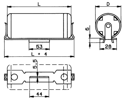
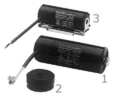
| 1 Capac. type 04P - 2 End cap - 3 Metal bracket: Four different mounting positions for capacitors size 3 and 4 - One position for size 5 and 6. See dimensions table 1 in the next page. | ||||||||||||||||||||||||||||||||||||||||||||||||||||||||||||||||||||||||||||||||||||||||||||||||||||||||||||
| V.ac 125 - V.ac 160 - V.ac 220 - V.ac 260 - V.ac 280 - V.ac 260/300** - V.ac 330 | ||||||||||||||||||||||||||||||||||||||||||||||||||||||||||||||||||||||||||||||||||||||||||||||||||||||||||||
| APPLICATIONS | ||||||||||||||||||||||||||||||||||||||||||||||||||||||||||||||||||||||||||||||||||||||||||||||||||||||||||||
| The FACON AC. motor start capacitors are
non-polar aluminium electrolytic capacitors designed for intermittent AC. duty, more
specifically, the starting of small AC. motors. Other applications: - Filtering alternating current (for ex: soldering units) - f £ 20 KHz - Filtering V.DC with high superimposed V.AC - f £ 1 KHz - Continuous voltage with reversed polarity - On request, some values can be used under continuous V.AC £ 48 V - f = 50 £ ÷ 20.000 Hz - see enclosure 3/A |
||||||||||||||||||||||||||||||||||||||||||||||||||||||||||||||||||||||||||||||||||||||||||||||||||||||||||||
| MANUFACTURING | ||||||||||||||||||||||||||||||||||||||||||||||||||||||||||||||||||||||||||||||||||||||||||||||||||||||||||||
| These capacitors are interely realized with plastic case and assembled with automatic machines to guarantee a costant quality. Facon Type 04P. capacitors are normally supplied with end cup and double faston terminals (6.3 x 0.8 mm.). On request: simple faston, bipolar cable, discharge resistance, metal mounting bracket for capacitors size 3, 4, 5 - fixing stud M8x10 mm. for capacitors size C, D, E. | ||||||||||||||||||||||||||||||||||||||||||||||||||||||||||||||||||||||||||||||||||||||||||||||||||||||||||||
| TECHNICAL CHARACTERISTICS | ||||||||||||||||||||||||||||||||||||||||||||||||||||||||||||||||||||||||||||||||||||||||||||||||||||||||||||
| See tables 2) 3) and enclosure 1/A. | ||||||||||||||||||||||||||||||||||||||||||||||||||||||||||||||||||||||||||||||||||||||||||||||||||||||||||||
| MEASUREMENTS | ||||||||||||||||||||||||||||||||||||||||||||||||||||||||||||||||||||||||||||||||||||||||||||||||||||||||||||
Using the circuit shown, apply rated voltage
to the capacitor and measure current and dissipated power. Current will be measured after
2 ÷ 3 seconds, dissipated power within 3 seconds after application of rated voltage.
Capacitance and power factor must be calculed with the wollowing formula: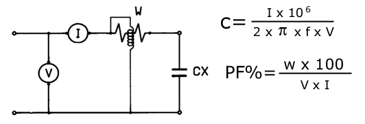 |
||||||||||||||||||||||||||||||||||||||||||||||||||||||||||||||||||||||||||||||||||||||||||||||||||||||||||||
| where: C = capacitance in µ F -
I = current in amperes - p = constant 3.14 -
f = frequency in hertz - V = applied voltage - PF = power factor - W = dissipated power in Watts |
||||||||||||||||||||||||||||||||||||||||||||||||||||||||||||||||||||||||||||||||||||||||||||||||||||||||||||
| Note: to have the right measurements is required a special type of instruments. | ||||||||||||||||||||||||||||||||||||||||||||||||||||||||||||||||||||||||||||||||||||||||||||||||||||||||||||
|
||||||||||||||||||||||||||||||||||||||||||||||||||||||||||||||||||||||||||||||||||||||||||||||||||||||||||||